立方体贴图是一种纹理类型,它包含了6个2D纹理,每个2D纹理作为立方体六个面中的一张贴图
立方体贴图采样的方式如下图所示:
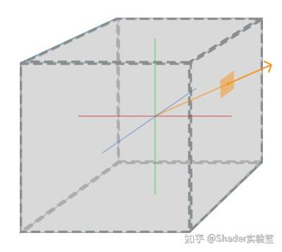
假设上图是由六张纹理所组成的立方体贴图,通过立方体中心投射方向向量,当投射的方向向量击中了立方体中的某个位置时,该位置就是我们想要的纹素,即最终生成的纹理值。通过“方向向量”,“立方体”等线索,我们发现:当把立方体模型(大小不重要)放置于坐标系中心时,立方体模型上的顶点坐标(包括通过重心坐标插值后的顶点坐标)与坐标中心相减后即可生成方向向量。
分析到这里,我们知道了如果要实现立方体贴图功能,需要三个条件:
1.6张2D贴图构成立方体贴图
2.生成立方体模型,模型坐标中心为立方体模型中心,并放置该模型至世界坐标中心位置
3.立方体模型顶点坐标作为立方体贴图的UV坐标
根据条件,我们需要加载6张的2D纹理贴图,并将其上传至gpu空间中:
<img src="map_back.png" id="cube01_back" style="display:none;">
<img src="map_front.png" id="cube01_front" style="display:none;">
<img src="map_bottom.png" id="cube01_bottom" style="display:none;">
<img src="map_left.png" id="cube01_left" style="display:none;">
<img src="map_right.png" id="cube01_right" style="display:none;">
<img src="map_top.png" id="cube01_top" style="display:none;">

gl.fLoadCubeMap = function(name, imgArray) {
        if(imgArray.length != 6) return null;
        let tex = this.createTexture();
        this.bindTexture(this.TEXTURE_CUBE_MAP, tex);
        for(let i = 0; i<6; i++) {
            this.texImage2D(this.TEXTURE_CUBE_MAP_POSITIVE_X+i, 0, this.RGBA, this.RGBA, this.UNSIGNED_BYTE, imgArray[i]);
        }

        this.texParameteri(this.TEXTURE_CUBE_MAP, this.TEXTURE_MAG_FILTER, this.LINEAR);
        this.texParameteri(this.TEXTURE_CUBE_MAP, this.TEXTURE_MIN_FILTER, this.LINEAR);
        this.texParameteri(this.TEXTURE_CUBE_MAP, this.TEXTURE_WARP_S, this.CLAMP_TO_EDGE);
        this.texParameteri(this.TEXTURE_CUBE_MAP, this.TEXTURE_WARP_T, this.CLAMP_TO_EDGE);
        this.texParameteri(this.TEXTURE_CUBE_MAP, this.TEXTURE_WARP_R, this.CLAMP_TO_EDGE);

        this.bindTexture(this.TEXTURE_CUBE_MAP, null);
        this.mTextureCache[name] = tex;
        return tex;
}

gl.fLoadCubeMap("skybox", [
        document.getElementById("cube01_right"), document.getElementById("cube01_left"),
        document.getElementById("cube01_top"), document.getElementById("cube01_bottom"),
        document.getElementById("cube01_back"), document.getElementById("cube01_front"),
]);
在fLoadCubeMap函数中,我们通过createTexture()生成WebglTexture,通过bindTexture(this.TEXTURE_CUBE_MAP, tex)与其绑定,通过texImage2D(this.TEXTURE_CUBE_MAP_POSITIVE_X+i,0,this.RGBA,this.RGBA,this.UNSIGNED_BYTE, imgArray[i])调用6次glTexImage2D函数,将纹理目标第一个参数(target)参数设置为立方体贴图的一个特定面,它告诉WebGL是在对立方体贴图的哪一个面创建纹理。
WebGL提供了6个特殊的纹理目标,各分别对应立方体贴图的一个面。
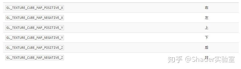
由于上表中属性的枚举值是由上往下递增的,所以可以通过对TEXTURE_CUBE_MAP_POSITIVE_X递增来实现对CubeMap各个不同面的赋值。
立方体贴图也是普通贴图构成的,所以它的环绕与过滤方式与普通纹理没有其他区别,主要区别在于增加了texParameteri(this.TEXTURE_CUBE_MAP,this.TEXTURE_WARP_R,this.CLAMP_TO_EDGE)这行代码,TEXTURE_WARP_R与TEXTURE_WARP_S或TEXTURE_WARP_T并没有本质上的区别,R只是纹理坐标在z方向上的表示。
如果是在原生层实现天空盒,最好开启glEnable(GL_TEXTURE_CUBE_MAP_SEAMLESS);开启后天空盒六个面间的像素将使用双线性插值过滤,将生成无缝的CubeMap。
到此CubeMap数据已准备完毕,要使用它还需要定义一个立方体模型及处理CubeMap的着色器,首先是立方体模型的生成:
static createMesh(gl,name,width,height,depth,x,y,z) {
        let w = width * 0.5, h = height * 0.5, d = depth * 0.5;
        let x0 = x-w, x1 = x+w, y0 = y-h, y1 = y+h, z0 = z-d, z1 = z+d;
        var aVert = [
			x0, y1, z1, 0,	//0 Front
			x0, y0, z1, 0,	//1
			x1, y0, z1, 0,	//2
			x1, y1, z1, 1,	//3

			x1, y1, z0, 1,	//4 Back
			x1, y0, z0, 1,	//5
			x0, y0, z0, 1,	//6
			x0, y1, z0, 0,	//7

			x0, y1, z0, 2,	//7 Left
			x0, y0, z0, 2,	//6
			x0, y0, z1, 2,	//1
			x0, y1, z1, 1,	//0

			x0, y0, z1, 3,	//1 Bottom
			x0, y0, z0, 3,	//6
			x1, y0, z0, 3,	//5
			x1, y0, z1, 2,	//2

			x1, y1, z1, 4,	//3 Right
			x1, y0, z1, 4,	//2
			x1, y0, z0, 4,	//5
			x1, y1, z0, 3,	//4

			x0, y1, z0, 5,	//7 Top
			x0, y1, z1, 5,	//0
			x1, y1, z1, 5,	//3
			x1, y1, z0, 1	//4
		];
        //Build the index of each quad [0,1,2, 2,3,0]
        var aIndex = [];
        for(var i=0; i < aVert.length / 4; i+=2) aIndex.push(i, i+1, (Math.floor(i/4)*4)+((i+2)%4));

        //Build UV data for each vertex
        var aUV = [];
        for(var i=0; i < 6; i++) aUV.push(0,0,	0,1,  1,1,  1,0);

        //Build Normal data for each vertex
        var aNorm = [
            0, 0, 1,	 0, 0, 1,	 0, 0, 1,	 0, 0, 1,		//Front
            0, 0,-1,	 0, 0,-1,	 0, 0,-1,	 0, 0,-1,		//Back
            -1, 0, 0,	-1, 0, 0,	-1, 0,0 ,	-1, 0, 0,		//Left
            0,-1, 0,	 0,-1, 0,	 0,-1, 0,	 0,-1, 0,		//Bottom
            1, 0, 0,	 1, 0, 0,	 1, 0, 0,	 1, 0, 0,		//Right
            0, 1, 0,	 0, 1, 0,	 0, 1, 0,	 0, 1, 0		//Top
        ]

        var mesh = gl.fCreateMeshVAO(name,aIndex,aVert,aNorm,aUV, 4);
        mesh.noCulling = true;
        return mesh;
    }
生成立方体模型需要记住的一点是模型之间不要共用顶点,否则无法生成有效的Skybox,如以下代码是通过ibo共用顶点的方式:
static createMesh(gl) {
        let aVert = [
            -0.5,0.5,0,0, -0.5,-0.5,0,0, 0.5,-0.5,0,0, 0.5,0.5,0,0,
            0.5,0.5,-1,1, 0.5,-0.5,-1,1, -0.5,-0.5,-1,1, -0.5,0.5,-1,1
        ],
        aUV = [
            0,0, 0,1, 1,1, 1,1,
            0,0, 0,1, 1,1, 1,0,
        ],
        aIndex = [
            0,1,2, 2,3,0, // Front
            4,5,6, 6,7,4, // Back
            3,2,5, 5,4,3, // Right
            7,0,3, 3,4,7, // Top
            7,6,1, 1,0,7,  // Left
            2,6,5, 6,2,1 // Bottom
        ];
        return gl.fCreateMeshVAO("cubeBad", aIndex, aVert, null, aUV, 4);
    }
为什么不要共用顶点?我们知道顶点与顶点间是通过插值的方式生成的(如:重心坐标方式),如果共用了顶点,那么UV坐标乃至顶点坐标都会自动插值生成,那么共用顶点部分的UV或顶点坐标的最终生成往往不是我们自己想要的,所以SkyBox立方体模型的生成不要使用共用顶点的方式。
生成了立方体模型后,就需要先把准备好的纹理激活,然后把纹理与模型数据扔到管线中。
先激活纹理:
let cubemap = gl.getUniformLocation(this.program, "uCubemap");

this.gl.activeTexture(this.gl.TEXTURE0);
this.gl.bindTexture(this.gl.TEXTURE_CUBE_MAP, cubeMapTexId);
this.gl.uniform1i(cubemap, 0);
创建顶点与片元着色器:
// 顶点着色器
#version 300 es
in vec4 a_position;
in vec2 a_uv;

uniform mat4 uPMatrix;
uniform mat4 uMVMatrix;
uniform mat4 uCameraMatrix;

out highp vec3 texCoord;  //Interpolate UV values to the fragment shader

void main(void){
     texCoord = a_position.xyz;
     vec4 pos = uPMatrix * uCameraMatrix * vec4(a_position.xyz, 1.0);
     gl_Position = pos;
}

// 片元着色器
#version 300 es
precision mediump float;

in highp vec3 texCoord;
uniform samplerCube uCubemap;。

out vec4 finalColor;
void main(void){
     finalColor = texture(uCubemap, texCoord);
}
texCoord = a_position.xyz这行代码直接把顶点坐标作为CubeMap的纹理坐标,与2D纹理使用sampler2D不同,CubeMap使用samplerCube 采样器定义。
运行后发现相机的移动会改变SkyBox的视角,而我们需要的是转动相机才改变视角,所以在传递相机矩阵的时候我们应该剔除translate部分:
getTranslatelessMatrix() {
	let mat = new Float32Array(this.viewMatrix);
	mat[12] = mat[13] = mat[14] = 0.0;
	return mat;
}
剔除后,发现移动相机已经不会改变视角了,但是发现移动相机超出立方体模型大小时,场景物体会被SkyBox遮挡,此时需要关闭depthMask,禁用深度写入。
gl.depthMask(false)
这种方式要求SkyBox得最先渲染,原因很简单,后渲染会覆盖先渲染的物体,所以如果SkyBox不是放在最开始的地方渲染,那么就会把之前渲染的物体覆盖了,为了解决这个问题,我们可以改动下顶点着色器:
void main(void){
     texCoord = a_position.xyz;
     vec4 pos = uPMatrix * uCameraMatrix * vec4(a_position.xyz, 1.0);
     gl_Position = pos.xyww;
}
我们把gl_Position的z坐标设置为w值,这是因为顶点着色器运行后会进行透视除法的运算,得出结果的z分量等于顶点的深度值,透视除法执行时,z分量就等于w / w = 1,最终在标准化设备坐标中就会有一个恒等于1的z值,也就是最大的深度值。这么做除了可以无视渲染顺序外,还可以对管线的细节进行优化,减少片元着色器的调用,这种优化方式也叫做提前深度测试(Early Depth Testing),它可以帮助物体减少片元着色器的调用。最后再修改下depthFunc,那么深度缓冲将会填充上天空盒的1.0值:
gl.depthFunc(gl.LEQUAL);
感兴趣的话关注下我们吧!