这是某天一朋友让帮忙看的一个功能,大概就是想要一个在运行时可以可视化看到模型是否在特定Camera的 Frustum内的逻辑,功能不难,但是有些点需要注意下,整理出来做个简单记录。
听到这个逻辑需求,很容易能想到,不就是类似引擎编辑器相机的可视化需求么?
不过这位朋友不想用特定图标来表示相机,而是希望直接用顶点数据来绘制相机,另外模型是否在Frustum内需要能够清晰的可以让用户看到,所以决定分成两步,先实现类似引擎编辑器相机的可视化功能。
基于上述功能,进行迭代。

这样模型出入Frustum就可以看到了 。

开始功能之前需要了解MVP矩阵的作用是将模型从其本地坐标系变换到裁剪坐标系(Clip Space)中的立方体(范围为[-w, w]³)的过程,其中w值可以理解为是在MV矩阵变换顶点后的z值坐标,顶点到相机的距离越远,w的值就越大。接着通过透视除法操作,即将裁剪空间中的坐标除以w,以得到NDC坐标,这个立方体就称为规范化设备坐标(Normalized Device Coordinates,NDC),在NDC坐标系中,其范围是从-1到1的立方体。
基于上述的理论,我们可以定义一个以[-1, 1]³的立方体为边界的顶点数据,通过乘于VP矩阵的逆矩阵把该顶点数据变换为世界坐标即可绘制Frustum。
我们定义两个部分的顶点数据,一个用来表示相机图标的Gizmo,一个用来描述Frustum:
    void createCameraGizmo()
    {
        // 定义顶点数据
        gizmoVertices = new List<Vector3> {
            new Vector3(-1, -1,  1), //0
            new Vector3( 1, -1,  1),//1
            new Vector3(-1,  1,  1), //2
            new Vector3( 1,  1,  1),//3
            new Vector3(-1, -1,  3),//4
            new Vector3( 1, -1,  3),//5
            new Vector3(-1,  1,  3),//6
            new Vector3( 1,  1,  3),//7
            new Vector3( 0,  0,  1),//8(视锥顶点)
        };

        // 定义索引数据
        gizmoIndices = new List<int> {
            0, 1, 1,
            3, 3, 2,
            2, 0, 4,
            5, 5, 7,
            7, 6, 6,
            4, 0, 4,
            1, 5, 3,
            7, 2, 6,
        };
        // 描述相机Gizmo的朝向
        int numSegments = 6;
        int coneBaseIndex = gizmoVertices.Count * 3 / 3;
        int coneTipIndex = coneBaseIndex - 1;
        for (int i = 0; i < numSegments; ++i)
        {
            float u = (float)i / (float)numSegments;
            float angle = u * Mathf.PI * 2.0f;
            float x = Mathf.Cos(angle);
            float y = Mathf.Sin(angle);
            gizmoVertices.Add(new Vector3(x, y, 0));
            // 从顶点到锥体边缘的连线
            gizmoIndices.Add(coneTipIndex);
            gizmoIndices.Add(coneBaseIndex + i);
            // 锥体底边的连线
            gizmoIndices.Add(coneBaseIndex + i);
            gizmoIndices.Add(coneBaseIndex + (i + 1) % numSegments);
        }
        // 通过获取相机的世界矩阵来确定gizmo的位置,旋转及缩放
        Matrix4x4 worldMatrix = cam.transform.localToWorldMatrix;
        for (int vi = 0; vi < gizmoVertices.Count; vi++)
        {
            // 其中scale可以适当调整gizmo的大小到合适位置
            gizmoVertices[vi] = worldMatrix.MultiplyPoint(gizmoVertices[vi] * scale);
        }
    }
    // 获取目标相机VP的逆矩阵
    Matrix4x4 getProViewInvMat()
    {
        Matrix4x4 projectionMatrix = cam.projectionMatrix;
        Matrix4x4 viewMatrix = cam.worldToCameraMatrix;
        Matrix4x4 vpMatrix = projectionMatrix * viewMatrix;
        Matrix4x4 invVpMatrix = Matrix4x4.Inverse(vpMatrix);
        return invVpMatrix;
    }
    // 通过顶点数据创建Frustum
    void createFrustum()
    {
        // [-1, 1]³范围顶点数据
        frustumVertices = new List<Vector3> {
            new Vector3(-1, -1, -1), //0
            new Vector3(1, -1, -1),//1
            new Vector3(-1,  1, -1), //2
            new Vector3(1,  1, -1),//3
            new Vector3(-1, -1,  1),//4
            new Vector3(1, -1,  1),//5
            new Vector3(-1,  1,  1),//6
            new Vector3(1,  1,  1),//7
        };
        // 顶点索引
        frustumIndices = new List<int> {
            0, 1, 1, 3, 3, 2, 2, 0,
            4, 5, 5, 7, 7, 6, 6, 4,
            0, 4, 1, 5, 3, 7, 2, 6,
        };

        Matrix4x4 invVpMatrix = getProViewInvMat();
        for (int vi = 0; vi < frustumVertices.Count; vi++)
        {
            // 通过VP矩阵的逆矩阵还原为Frustum,不要使用MultiplyVector以及*符号
            Vector4 frustumPos = invVpMatrix.MultiplyPoint(frustumVertices[vi]);
            frustumVertices[vi] = frustumPos;
        }
    }
    // 指定目标gameobject,shader,顶点与索引数据生成mesh与材质
    Material generateMesh(GameObject obj, string shader, List<Vector3> vertices, List<int> indices)
    {
        Mesh gizmoMesh = new Mesh();
        gizmoMesh.vertices = vertices.ToArray();
        gizmoMesh.SetIndices(indices, MeshTopology.Lines, 0);
        MeshFilter gizmoMeshFilter = obj.AddComponent<MeshFilter>();
        gizmoMeshFilter.mesh = gizmoMesh;
        MeshRenderer meshRenderer = obj.AddComponent<MeshRenderer>();
        Material material = new Material(Shader.Find(shader));
        meshRenderer.material = material;
        return material;
    }
    void Start()
    {
        createCameraGizmo();
        createFrustum();
        gizmoMaterial = generateMesh(gameObject, "Unlit/Color", gizmoVertices, gizmoIndices);
        GameObject frustumObj = new GameObject("Frustum");
        frustumObj.transform.parent = transform;
        frustumMaterial = generateMesh(frustumObj, "Unlit/Color", frustumVertices, frustumIndices);
    }
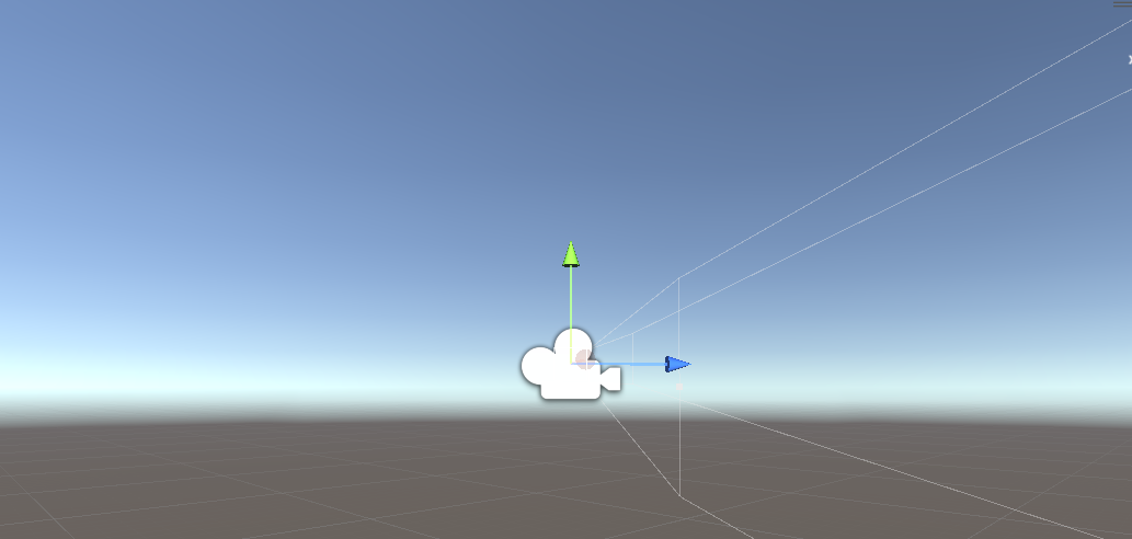
通过该方式运行后发现gizmo的朝向反了:
这是因为我们把gizmo的顶点数据乘上了目标相机的localToWorldMatrix矩阵,而相机的朝向是指向相机自身坐标系的-z轴方向,所以我们需要把这些附带的条件考虑进去,部分代码修改为:
    void createCameraGizmo()
    {
        // ...
        Matrix4x4 viewMatrix = cam.cameraToWorldMatrix;// 或则cam.worldToCameraMatrix.inverse
        for (int vi = 0; vi < gizmoVertices.Count; vi++)
        {
            gizmoVertices[vi] = viewMatrix.MultiplyPoint(gizmoVertices[vi] * scale);
        }
    }
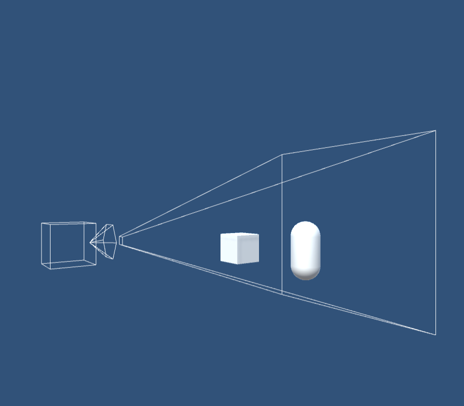
这时候就正确了:

但是发现移动目标相机后线框没有跟着移动,原因是我们只在程序开始的时候设定了顶点数据,所以移动相机后数据还是原来的,不过如果每帧都在cpu内存中更新顶点数据毕竟是负担,所以这一步就交给Shader来完成:
GizmoShader
// 目标相机的cameraToWorldMatrix矩阵
uniform float4x4 targetViewInv;
// gizmo的缩放值
uniform float scale;
v2f vert (appdata v)
{
    v2f o;
    o.vertex = UnityObjectToClipPos(mul(targetViewInv, float4(v.vertex.x * scale, v.vertex.y * scale, v.vertex.z * scale, 1.0)));
    o.uv = TRANSFORM_TEX(v.uv, _MainTex);
    UNITY_TRANSFER_FOG(o,o.vertex);
    return o;
}
FrustumShader
// 目标相机的VP矩阵的逆矩阵
uniform float4x4 targetProjViewInv;
v2f vert (appdata v)
{
     v2f o;
     // 目标相机的VP逆矩阵求取世界空间中的坐标
     float4 currVer = mul(targetProjViewInv, float4(v.vertex.x, v.vertex.y, v.vertex.z, 1.0));
     // 需要除以w
     float wNum = 1.0 / currVer.w;
     o.vertex = UnityObjectToClipPos(float3(currVer.x * wNum, currVer.y * wNum, currVer.z * wNum));
     o.uv = TRANSFORM_TEX(v.uv, _MainTex);
     UNITY_TRANSFER_FOG(o,o.vertex);
     return o;
}
然后修改Start函数以及Update函数:
void Start()
{
        createCameraGizmo();
        createFrustum();
        gizmoMaterial = generateMesh(gameObject, "Custom/GizmoShader", gizmoVertices, gizmoIndices);
        // 传递目标相机的View的逆矩阵
        gizmoMaterial.SetMatrix("targetViewInv", cam.worldToCameraMatrix.inverse);
        // 传递scale的值
        gizmoMaterial.SetFloat("scale", scale);
        GameObject frustumObj = new GameObject("Frustum");
        frustumObj.transform.parent = transform;
        frustumMaterial = generateMesh(frustumObj, "Custom/FrustumShader", frustumVertices, frustumIndices);
        // 传递目标相机的ViewProj的逆矩阵
        frustumMaterial.SetMatrix("targetProjViewInv", getProViewInvMat());
}
private void Update()
{
        gizmoMaterial.SetMatrix("targetViewInv", cam.worldToCameraMatrix.inverse);
        gizmoMaterial.SetFloat("scale", scale);
        frustumMaterial.SetMatrix("targetProjViewInv", getProViewInvMat());
}
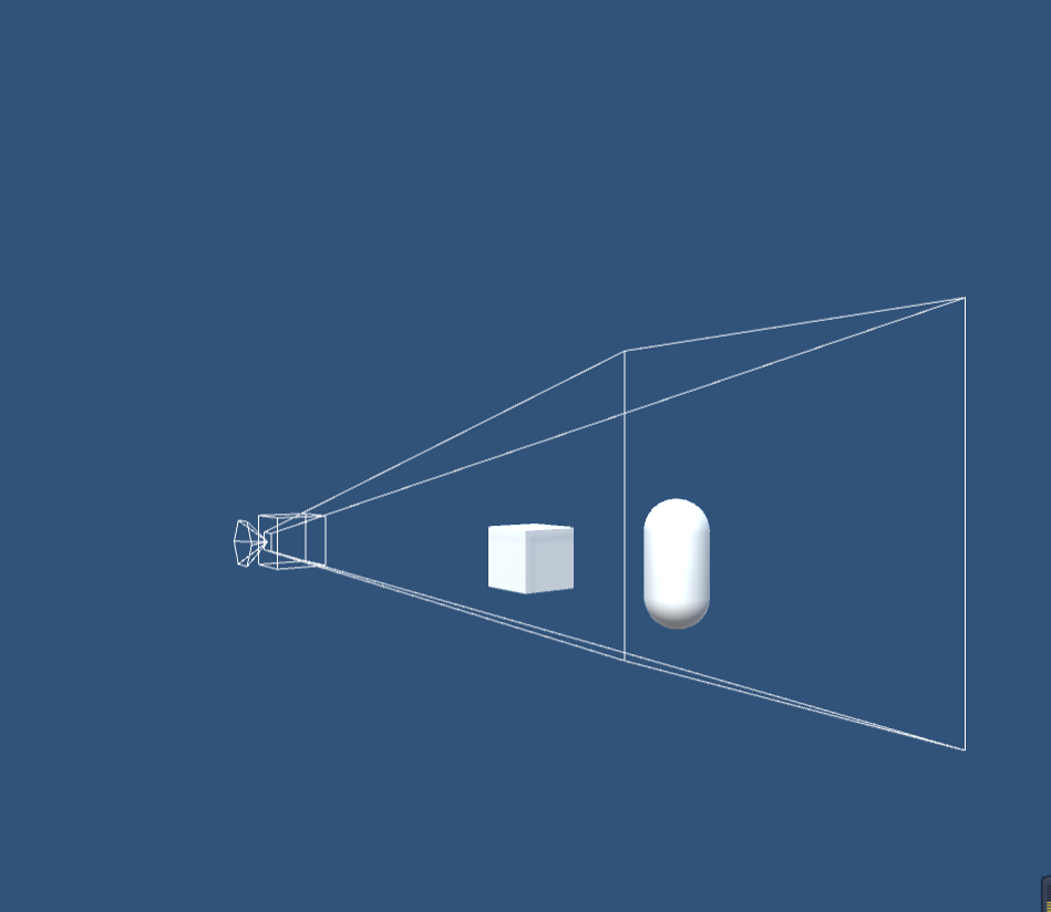
这样移动相机或调整相机的Fov等参数就可以同步数据了(代码没做优化,可自行调整)。
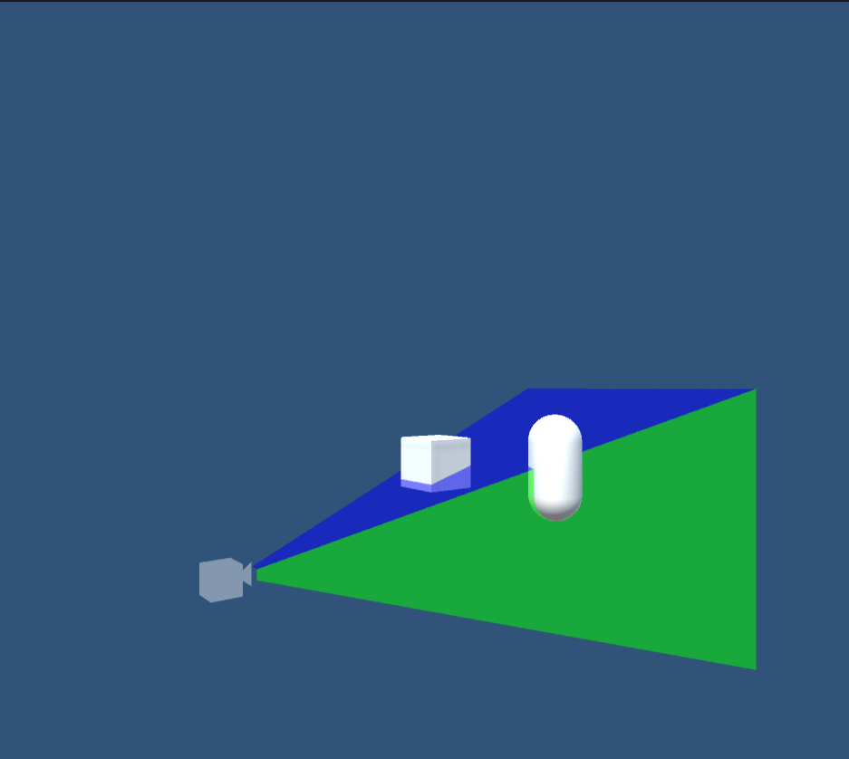
接下来就把线框改为三角面绘制, 并优化下顶点以及索引数据:
void createCameraGizmo()
{
        // Define the vertex data
        gizmoVertices = new List<Vector3> {
            // Cube Vertices
            new Vector3(-0.5f, -0.5f, 0f), // 0
            new Vector3(0.5f, -0.5f, 0f),  // 1
            new Vector3(-0.5f, 0.5f, 0f),  // 2
            new Vector3(0.5f, 0.5f, 0f),   // 3
            new Vector3(-0.5f, -0.5f, 1.0f),  // 4
            new Vector3(0.5f, -0.5f, 1.0f),   // 5
            new Vector3(-0.5f, 0.5f, 1.0f),   // 6
            new Vector3(0.5f, 0.5f, 1.0f),    // 7

            // Triangle Vertices
            new Vector3(0f, 0f, 0f),        // 8 (Triangle Vertex)
            new Vector3(0f, 0.4f, -0.5f),// 9 (Triangle Vertex)
            new Vector3(0f, -0.4f, -0.5f)  // 10 (Triangle Vertex)
        };

        // Define the index data
        gizmoIndices = new List<int> {
           // Cube Indices
            0, 1, 2, // Front Face
            1, 3, 2,
            4, 6, 5, // Back Face
            5, 6, 7,
            0, 4, 1, // Left Face
            4, 5, 1,
            2, 3, 6, // Right Face
            3, 7, 6,
            0, 2, 4, // Top Face
            2, 6, 4,
            1, 5, 3, // Bottom Face
            5, 7, 3,

            // Triangle Indices
            8, 9, 10,  // Triangle
            10, 9, 8
        };
}

void createFrustum()
{
        frustumVertices = new List<Vector3> {
            // Front Face
            new Vector3(-1, -1, 1),   // 左下
            new Vector3(1, -1, 1),    // 右下
            new Vector3(-1, 1, 1),    // 左上
            new Vector3(1, 1, 1),     // 右上

            // Back Face
            new Vector3(-1, -1, -1),  // 左下
            new Vector3(1, -1, -1),   // 右下
            new Vector3(-1, 1, -1),   // 左上
            new Vector3(1, 1, -1),    // 右上

            // Left Face
            new Vector3(-1, -1, -1),  // 左下
            new Vector3(-1, -1, 1),   // 右下
            new Vector3(-1, 1, -1),   // 左上
            new Vector3(-1, 1, 1),    // 右上

            // Right Face
            new Vector3(1, -1, 1),    // 左下
            new Vector3(1, -1, -1),   // 右下
            new Vector3(1, 1, 1),     // 左上
            new Vector3(1, 1, -1),    // 右上

            // Top Face
            new Vector3(-1, 1, 1),    // 左下
            new Vector3(1, 1, 1),     // 右下
            new Vector3(-1, 1, -1),   // 左上
            new Vector3(1, 1, -1),    // 右上

            // Bottom Face
            new Vector3(-1, -1, -1),  // 左下
            new Vector3(1, -1, -1),   // 右下
            new Vector3(-1, -1, 1),   // 左上
            new Vector3(1, -1, 1)     // 右上
        };
        frustumIndices = new List<int>{
            // Front Face
            0, 1, 2,
            2, 1, 3,

            // Back Face
            4, 5, 6,
            6, 5, 7,

            // Left Face
            8, 9, 10,
            10, 9, 11,

            // Right Face
            12, 13, 14,
            14, 13, 15,

            // Top Face
            16, 17, 18,
            18, 17, 19,

            // Bottom Face
            20, 21, 22,
            22, 21, 23
        };
        frustumColors = new List<Color>
        {
            // Front Face (Yellow)
            Color.yellow,
            Color.yellow,
            Color.yellow,
            Color.yellow,

            // Back Face (White)
            Color.white,
            Color.white,
            Color.white,
            Color.white,

            // Left Face (Red)
            Color.red,
            Color.red,
            Color.red,
            Color.red,

            // Right Face (Green)
            Color.green,
            Color.green,
            Color.green,
            Color.green,

            // Top Face (Blue)
            Color.blue,
            Color.blue,
            Color.blue,
            Color.blue,

            // Bottom Face (White)
            Color.white,
            Color.white,
            Color.white,
            Color.white
        };
}
然后把topology改为MeshTopology.Triangles,运行结果为:
这是代码。